
Most introductory DC circuit calculations can be reduced to a few relationships between voltage, current, resistance, and power. The SI units are volts (V), amperes (A), ohms (Ω), and watts (W). NIST defines the ohm as one volt per ampere and the volt as one watt per ampere.
The formulas themselves are short. The more useful skill is knowing when a formula applies. Ohm's law must use the voltage across and current through the same component or network. Series and parallel formulas depend on how the components are connected, while divider formulas assume a particular topology. Real voltage sources also have internal resistance, so a connected load can change the voltage that appears at the output.
Formula intuition
An electronic formula shows how quantities such as voltage, current, and resistance are related, and how changing one affects the others.
For an ideal resistor,
If the resistance stays fixed, doubling the current doubles the voltage across the resistor. If the voltage stays fixed, doubling the resistance halves the current. This proportional relationship is the basis of Ohm's law for an ohmic resistor.
Core circuit formulas
Ohm's Law
Start with:
Dividing both sides by gives current:
Dividing both sides by gives resistance:
Memo:
For example, a resistor with across it carries:
Resistors in series
Series components carry the same current. Their voltage drops add, so:
Using :
The common current cancels:
Resistors in parallel
Parallel branches have the same voltage. Their currents add:
Substitute :
Cancel :
For two resistors this reduces to:
The equivalent resistance of parallel branches is smaller than either branch resistance because adding another path allows more total current for the same applied voltage.
Voltage divider
Consider two series resistors:
The same current flows through both resistors:
The output voltage is the voltage across :
Substitute the first equation:
The voltage across each series resistor is therefore proportional to its resistance.
This equation describes the unloaded divider. Connecting another resistance from Vout to ground places that load in parallel with , changing the effective lower resistance and therefore changing .
Interactive animation
Current divider
For two parallel resistors, the same voltage appears across both branches:
The total current is:
For two branches, solving for the current through gives:
and similarly:
Current therefore divides inversely with resistance. The smaller branch resistance carries the larger current.
Electrical power
Electrical power is the rate at which electrical energy is transferred. Its SI unit is the watt, equal to one joule per second.
For a DC component:
Combining this with Ohm's law gives two useful forms.
Substitute :
so:
Or substitute :
giving:
These three equations describe the same resistor operating point. Choose the form that uses the quantities you already know.
Source and load models
An ideal voltage source maintains its specified voltage regardless of the current drawn from it. A simple model of a real voltage source adds a series internal resistance . MIT and OpenStax use this source-plus-series-resistance model when introducing non-ideal voltage sources.
Here is the load. The source resistance and load form a voltage divider:
and:
If is much larger than , little voltage is lost inside the source and is close to . As the load resistance falls, current rises and more voltage appears across the source resistance.
Worked example and bench experiment
Loading a voltage divider
A divider uses:
With no load:
Now connect a load from Vout to ground.
The load is parallel with :
The divider has changed to over :
The original calculation was correct only for the unloaded circuit. The load changed the circuit itself. This is the same principle behind source and load interaction: a finite resistance connected to an output affects the voltage whenever the source has non-zero output resistance.
Bench experiment: calculate, build, measure
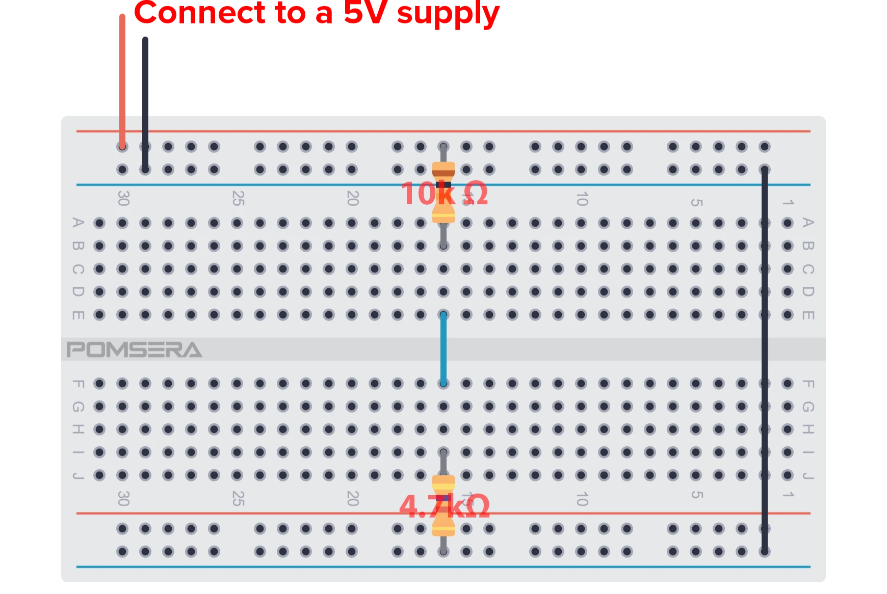
Use a low-voltage DC supply. Do not connect this experiment directly to mains electricity.
| Part | Quantity |
|---|---|
| 5 V DC bench supply | 1 |
| resistor | 1 |
| resistor | 1 |
| Breadboard | 1 |
| Digital multimeter | 1 |
Calculate the expected current through the two resistors, with and :
Then calculate the output voltage across :
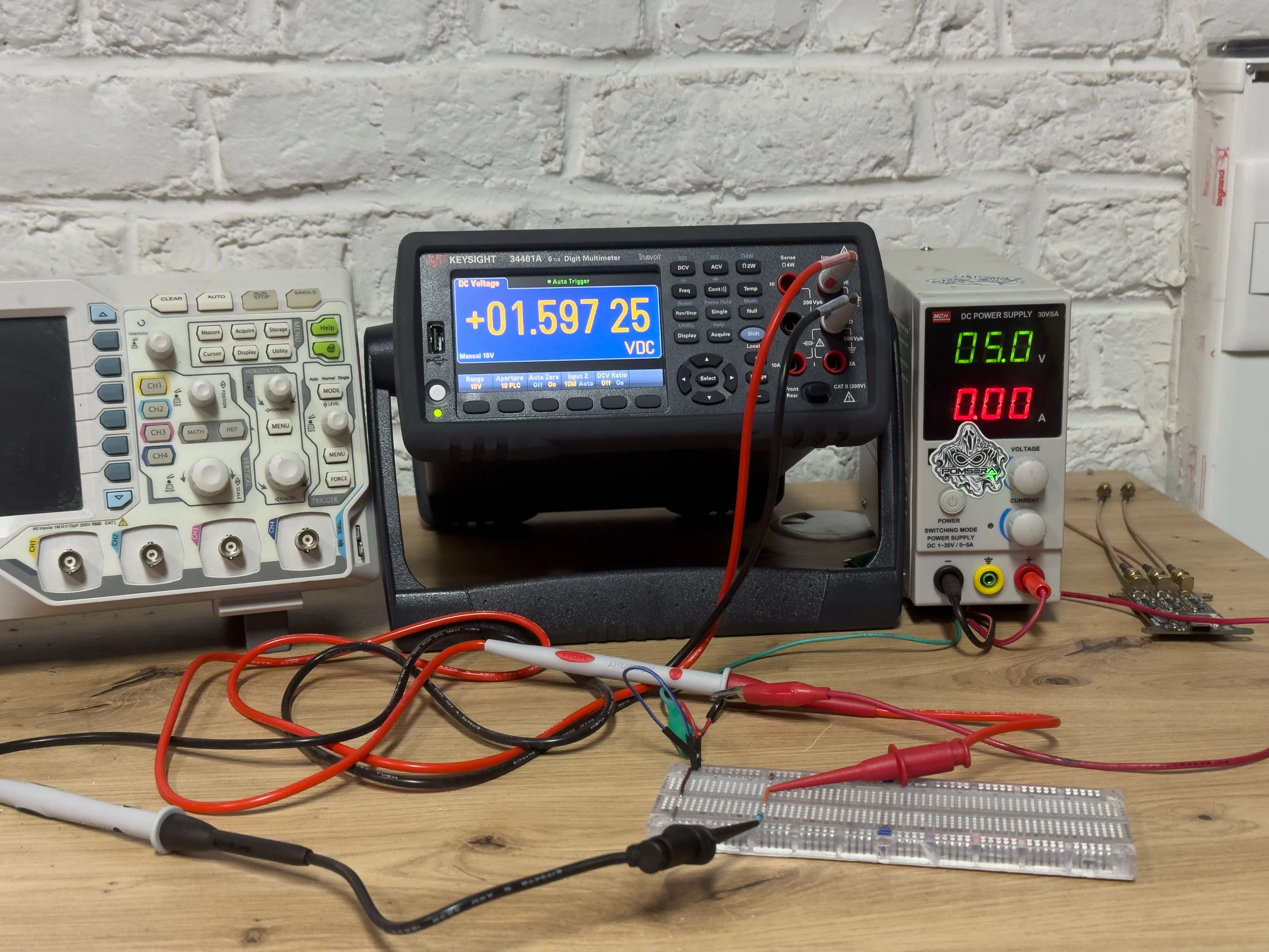
You should therefore expect a reading near 1.60 V. The measured value may differ slightly because of resistor tolerances and variations in the supply voltage.
Measure the supply voltage first, then switch off the power before assembling the voltage divider. Set the multimeter to DC voltage, connect the black probe to ground, and use the red probe to measure the junction between the two resistors.
Compare the measurement with the calculated value of 1.5986 V.
If the reading is approximately 0 V, check the connection between the supply and , and ensure the output is not accidentally shorted to ground. If it is close to 5 V, check that is correctly connected to ground.
For a more accurate comparison, measure the actual resistance of both resistors with the circuit powered off and repeat the calculation using those values.
Review questions
- Question 1 A resistor has across it. What current flows?A
- Question 2What is the equivalent resistance of and in series?Ω
- Question 3What is the equivalent resistance of two resistors in parallel?Ω
- Question 4A supply feeds two equal series resistors. What is the unloaded midpoint voltage?V
- Question 5Why can connecting a load reduce a divider's output voltage?
Summary
Ohm's law connects voltage, current and resistance:
Series resistances add directly, while parallel resistances add through their reciprocals. From those relationships come the voltage-divider and current-divider equations. Electrical power can be calculated as , , or when the values refer to the same resistor.
The equations are only as good as the model behind them. An unloaded voltage divider and a loaded voltage divider are different circuits. An ideal voltage source and a real source with internal resistance also produce different results under load. Learning to state those assumptions alongside the calculation is the habit that turns formula substitution into circuit analysis.